本帖最后由 177323106018214 于 2025-4-27 11:29 编辑
一、开箱
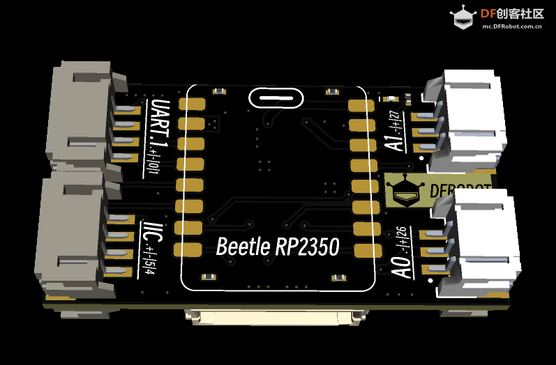
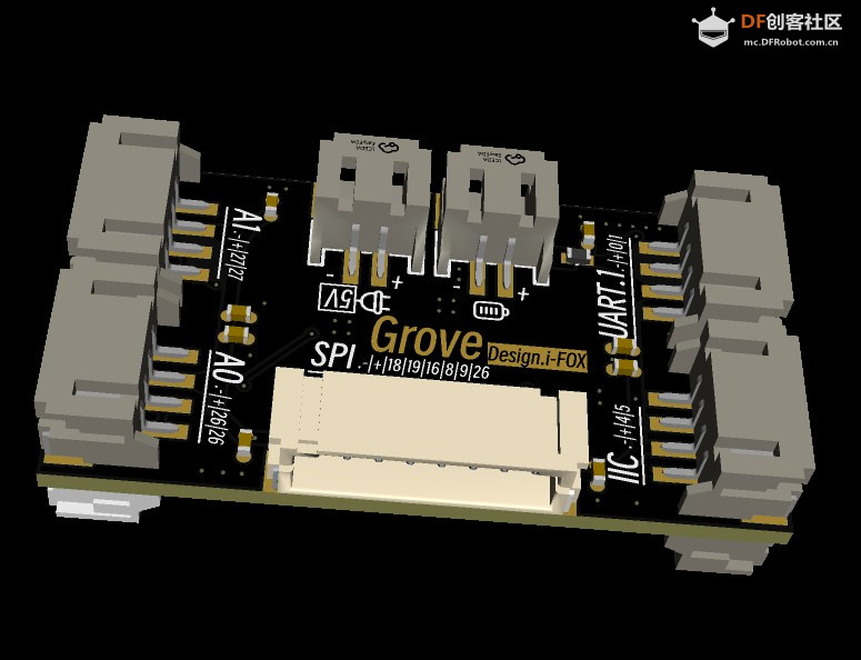
1、外形
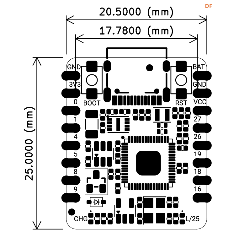 : :
2、原理图
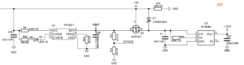
电源电路与双电源切换电路:
电池充电使用tp4057,3.3V 电源使用RT9080,供电能力有600mA。
双电源切换使用一个mos管,AO3407
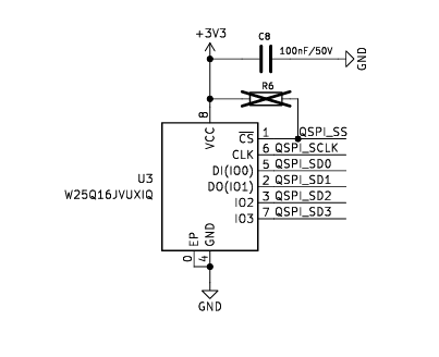
板载QSPI的存储芯片
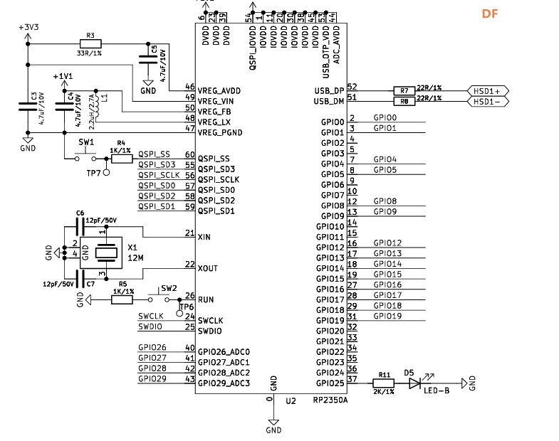
主控rp23502350,板载一个LED,接在了25引脚。可以看到很多的GPIO没有引出,为了板子的面积减小,做了一些取舍。
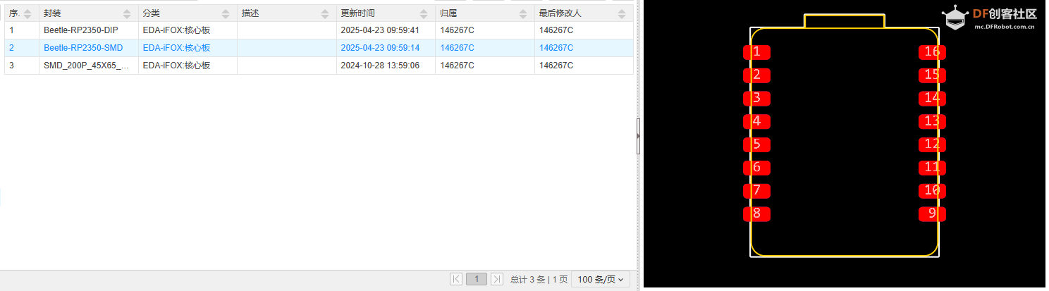
3、封装使用
官方提供的是kicad的,如果使用其他的软件需要转换,立创EDA支持从kicad直接导入。
二、Arduino开发
下载Arduino IDE,我使用的版本是2.3.5
菜单栏:文件->首选项,设置中开发板管理器地址输入如下地址:
https://github.com/earlephilhower/arduino-pico/releases/download/global/package_rp2040_index.json

确定后,会自动下载。
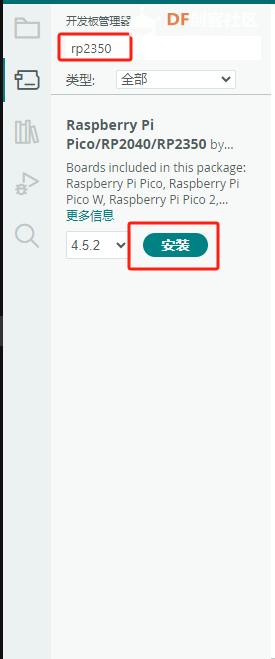
之后在开发板管理器中,查找rp2350就会有结果,直接安装。
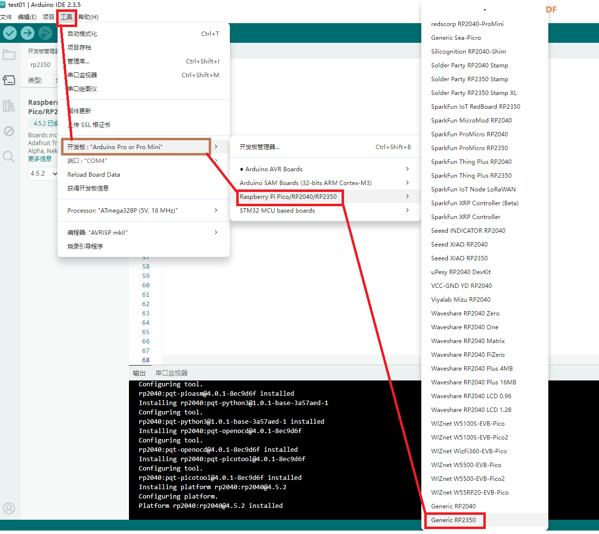
安装好后,可以在工具菜单下,选择开发板的型号与串口号。
开发板接入电脑后,会生成一个串口外设。
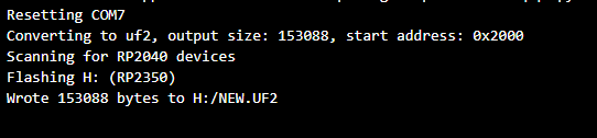
新建一个项目,测试一下blink的例程。烧写成功。
- void setup() {
- // put your setup code here, to run once:
- pinMode(LED_BUILTIN, OUTPUT);//设置引脚为输出模式
- }
-
- void loop() {
- // put your main code here, to run repeatedly:
- digitalWrite(LED_BUILTIN, HIGH); //输出高电平,点亮LED灯
- delay(200);
- digitalWrite(LED_BUILTIN, LOW); //输出低电平,熄灭LED灯
- delay(500);
- }
三、祼机开发
使用软件VScode
在VS Code的扩展中搜索:Raspberry Pi Pico
直接安装即可。安装过程会下载大量的库与工具,保证网络通畅。
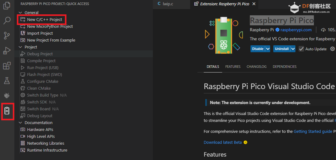
安装完成后,在左侧会有相应的图标,打开后,新建一个工程,就可以开始开发了。
可以使用C语言或是python进行开发。
有相应的SDK函数的说明文档。
python:datasheets.raspberrypi.com/pico/raspberry-pi-pico-python-sdk.pdf
C/C++:The C/C++ SDK - Raspberry Pi Documentation
这里进行一下测试。
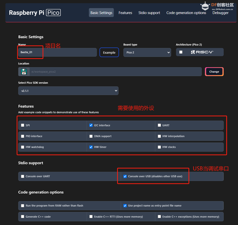
使用C进行开发,新建一个C的工程。
- #include <stdio.h>
- #include "pico/stdlib.h"
- #include "hardware/i2c.h"
- #include "hardware/timer.h"
-
- // I2C defines
- // This example will use I2C0 on GPIO8 (SDA) and GPIO9 (SCL) running at 400KHz.
- // Pins can be changed, see the GPIO function select table in the datasheet for information on GPIO assignments
- #define I2C_PORT i2c0
- #define I2C_SDA 8
- #define I2C_SCL 9
- #define BOARD_LED_PIN 25 //板载LED引脚
- #define LED_DELAY_MS 500
- int64_t alarm_callback(alarm_id_t id, void *user_data) {
- // Put your timeout handler code in here
- return 0;
- }
- //板载LED控制函数
- void pico_set_led(bool led_on)
- {
- gpio_put(BOARD_LED_PIN, led_on);
- }
-
-
- int main()
- {
- stdio_init_all();
-
- // I2C Initialisation. Using it at 400Khz.
- i2c_init(I2C_PORT, 400*1000);
-
- gpio_set_function(I2C_SDA, GPIO_FUNC_I2C);
- gpio_set_function(I2C_SCL, GPIO_FUNC_I2C);
- gpio_pull_up(I2C_SDA);
- gpio_pull_up(I2C_SCL);
-
- //LED Initialisation.on board pin 25
- gpio_init(BOARD_LED_PIN);
- gpio_set_dir(BOARD_LED_PIN, GPIO_OUT);
-
-
-
- // Timer example code - This example fires off the callback after 2000ms
- add_alarm_in_ms(2000, alarm_callback, NULL, false);
- // For more examples of timer use see https://github.com/raspberrypi/pico-examples/tree/master/timer
-
- while (true) {
- //printf("Hello, world!\n");
- pico_set_led(true);
- sleep_ms(LED_DELAY_MS);
- pico_set_led(false);
- sleep_ms(LED_DELAY_MS);
- }
- }
注意,第一次烧写时,需要按下boot按键,再上电,之后,再烧写时,可以直接点状态栏的 Run了。
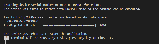

至此,rp2350的主要两种开发方式已经测试完成,都可以进行开发。
鉴于dfrobot社区 的生态与受众的差异,这里就选择Arduino的方式进行开发测试了。
另扩展板打样还在路上。只能用板载的LED外设进行测试了,等到货后进行其他测试。
| 

 沪公网安备31011502402448
 置顶卡
置顶卡 变色卡
变色卡 千斤顶
千斤顶