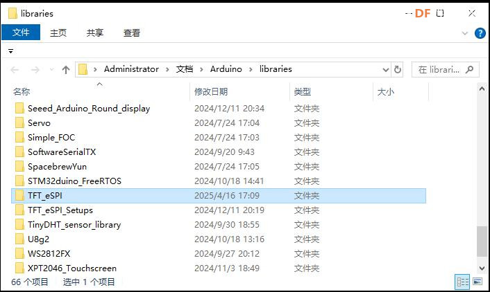
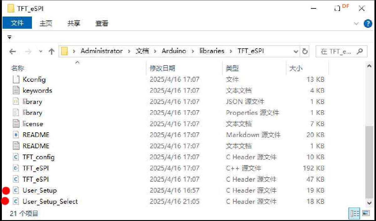
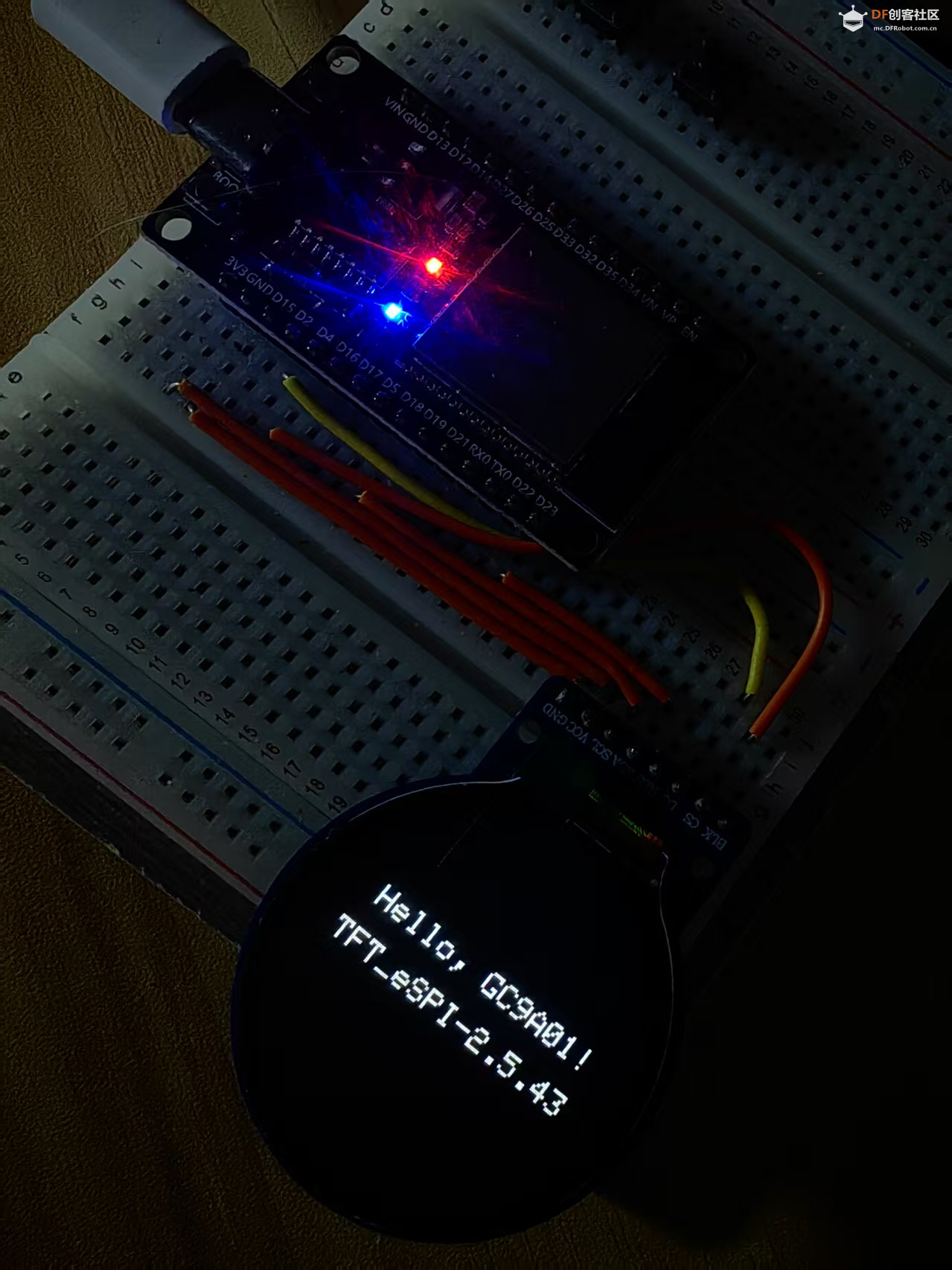
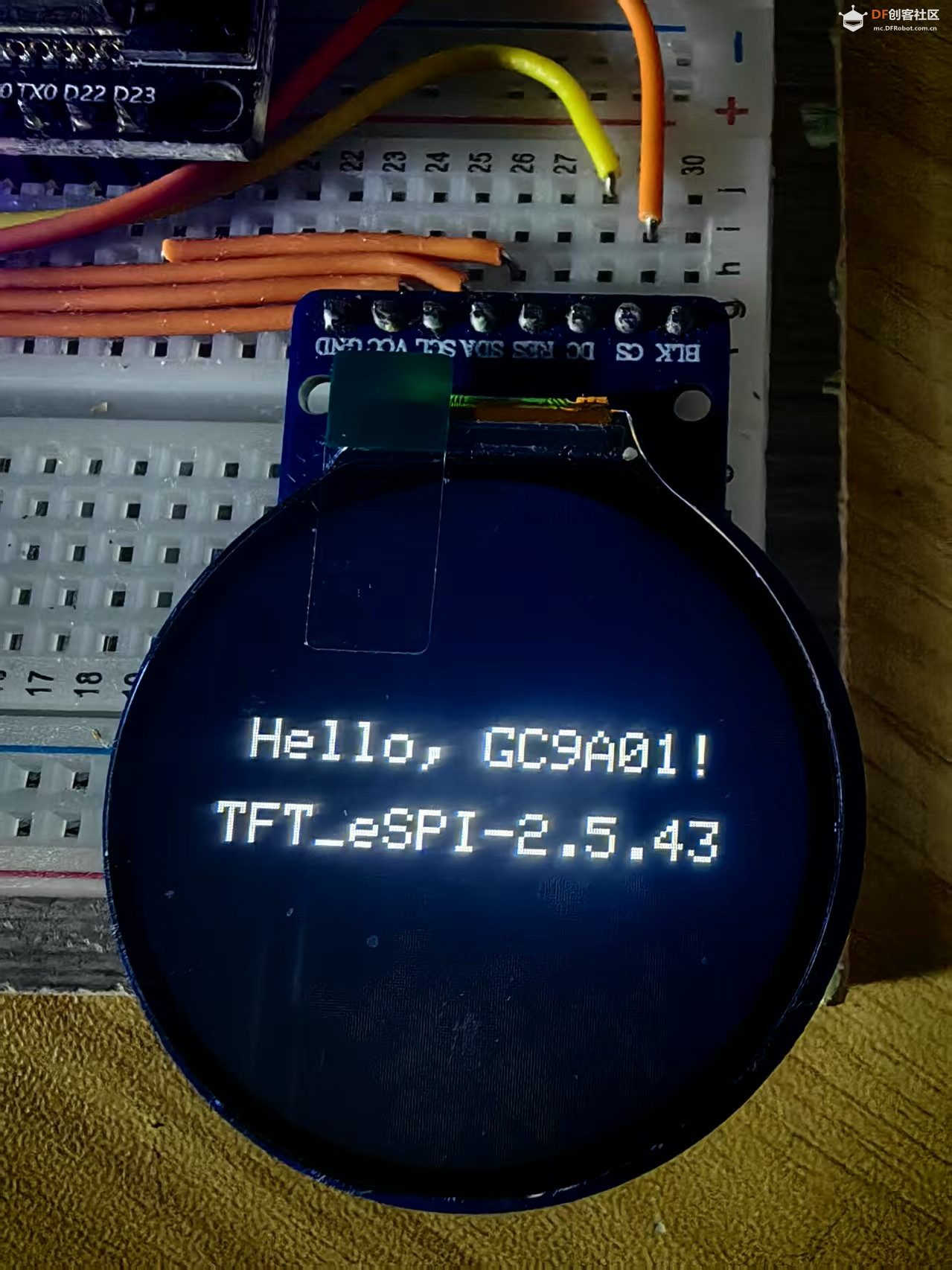
配置完毕的User_Setup.h完整代码如下:
- // USER DEFINED SETTINGS
- // Set driver type, fonts to be loaded, pins used and SPI control method etc.
- //
- // See the User_Setup_Select.h file if you wish to be able to define multiple
- // setups and then easily select which setup file is used by the compiler.
- //
- // If this file is edited correctly then all the library example sketches should
- // run without the need to make any more changes for a particular hardware setup!
- // Note that some sketches are designed for a particular TFT pixel width/height
-
- // User defined information reported by "Read_User_Setup" test & diagnostics example
- #define USER_SETUP_INFO "User_Setup"
-
- // Define to disable all #warnings in library (can be put in User_Setup_Select.h)
- //#define DISABLE_ALL_LIBRARY_WARNINGS
-
- // ##################################################################################
- //
- // Section 1. Call up the right driver file and any options for it
- //
- // ##################################################################################
-
- // Define STM32 to invoke optimised processor support (only for STM32)
- //#define STM32
-
- // Defining the STM32 board allows the library to optimise the performance
- // for UNO compatible "MCUfriend" style shields
- //#define NUCLEO_64_TFT
- //#define NUCLEO_144_TFT
-
- // STM32 8-bit parallel only:
- // If STN32 Port A or B pins 0-7 are used for 8-bit parallel data bus bits 0-7
- // then this will improve rendering performance by a factor of ~8x
- //#define STM_PORTA_DATA_BUS
- //#define STM_PORTB_DATA_BUS
-
- // Tell the library to use parallel mode (otherwise SPI is assumed)
- //#define TFT_PARALLEL_8_BIT
- //#defined TFT_PARALLEL_16_BIT // **** 16-bit parallel ONLY for RP2040 processor ****
-
- // Display type - only define if RPi display
- //#define RPI_DISPLAY_TYPE // 20MHz maximum SPI
-
- // Only define one driver, the other ones must be commented out
- //#define ILI9341_DRIVER // Generic driver for common displays
- //#define ILI9341_2_DRIVER // Alternative ILI9341 driver, see https://github.com/Bodmer/TFT_eSPI/issues/1172
- //#define ST7735_DRIVER // Define additional parameters below for this display
- //#define ILI9163_DRIVER // Define additional parameters below for this display
- //#define S6D02A1_DRIVER
- //#define RPI_ILI9486_DRIVER // 20MHz maximum SPI
- //#define HX8357D_DRIVER
- //#define ILI9481_DRIVER
- //#define ILI9486_DRIVER
- //#define ILI9488_DRIVER // WARNING: Do not connect ILI9488 display SDO to MISO if other devices share the SPI bus (TFT SDO does NOT tristate when CS is high)
- //#define ST7789_DRIVER // Full configuration option, define additional parameters below for this display
- //#define ST7789_2_DRIVER // Minimal configuration option, define additional parameters below for this display
- //#define R61581_DRIVER
- //#define RM68140_DRIVER
- //#define ST7796_DRIVER
- //#define SSD1351_DRIVER
- //#define SSD1963_480_DRIVER
- //#define SSD1963_800_DRIVER
- //#define SSD1963_800ALT_DRIVER
- //#define ILI9225_DRIVER
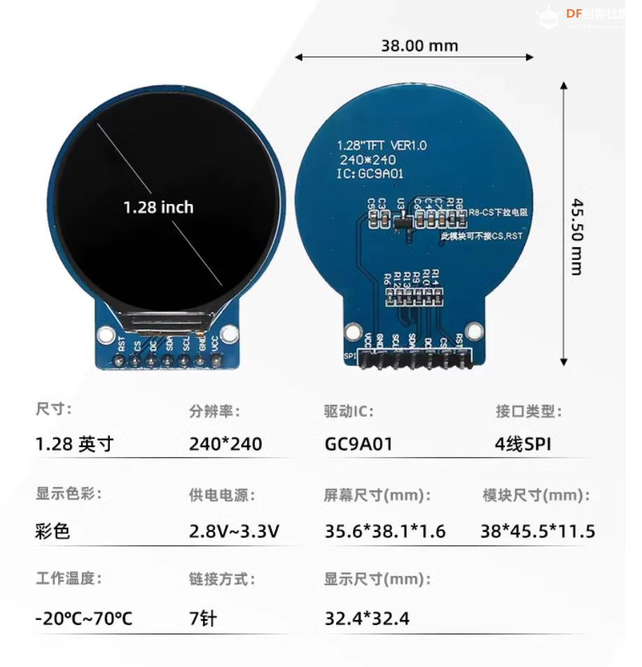
- #define GC9A01_DRIVER
-
- // Some displays support SPI reads via the MISO pin, other displays have a single
- // bi-directional SDA pin and the library will try to read this via the MOSI line.
- // To use the SDA line for reading data from the TFT uncomment the following line:
-
- // #define TFT_SDA_READ // This option is for ESP32 ONLY, tested with ST7789 and GC9A01 display only
-
- // For ST7735, ST7789 and ILI9341 ONLY, define the colour order IF the blue and red are swapped on your display
- // Try ONE option at a time to find the correct colour order for your display
-
- // #define TFT_RGB_ORDER TFT_RGB // Colour order Red-Green-Blue
- // #define TFT_RGB_ORDER TFT_BGR // Colour order Blue-Green-Red
-
- // For M5Stack ESP32 module with integrated ILI9341 display ONLY, remove // in line below
-
- // #define M5STACK
-
- // For ST7789, ST7735, ILI9163 and GC9A01 ONLY, define the pixel width and height in portrait orientation
- // #define TFT_WIDTH 80
- // #define TFT_WIDTH 128
- // #define TFT_WIDTH 172 // ST7789 172 x 320
- // #define TFT_WIDTH 170 // ST7789 170 x 320
- // #define TFT_WIDTH 240 // ST7789 240 x 240 and 240 x 320
- // #define TFT_HEIGHT 160
- // #define TFT_HEIGHT 128
- // #define TFT_HEIGHT 240 // ST7789 240 x 240
- // #define TFT_HEIGHT 320 // ST7789 240 x 320
- #define TFT_HEIGHT 240 // GC9A01 240 x 240
-
- // For ST7735 ONLY, define the type of display, originally this was based on the
- // colour of the tab on the screen protector film but this is not always true, so try
- // out the different options below if the screen does not display graphics correctly,
- // e.g. colours wrong, mirror images, or stray pixels at the edges.
- // Comment out ALL BUT ONE of these options for a ST7735 display driver, save this
- // this User_Setup file, then rebuild and upload the sketch to the board again:
-
- // #define ST7735_INITB
- // #define ST7735_GREENTAB
- // #define ST7735_GREENTAB2
- // #define ST7735_GREENTAB3
- // #define ST7735_GREENTAB128 // For 128 x 128 display
- // #define ST7735_GREENTAB160x80 // For 160 x 80 display (BGR, inverted, 26 offset)
- // #define ST7735_ROBOTLCD // For some RobotLCD Arduino shields (128x160, BGR, https://docs.arduino.cc/retired/getting-started-guides/TFT)
- // #define ST7735_REDTAB
- // #define ST7735_BLACKTAB
- // #define ST7735_REDTAB160x80 // For 160 x 80 display with 24 pixel offset
-
- // If colours are inverted (white shows as black) then uncomment one of the next
- // 2 lines try both options, one of the options should correct the inversion.
-
- // #define TFT_INVERSION_ON
- // #define TFT_INVERSION_OFF
-
-
- // ##################################################################################
- //
- // Section 2. Define the pins that are used to interface with the display here
- //
- // ##################################################################################
-
- // If a backlight control signal is available then define the TFT_BL pin in Section 2
- // below. The backlight will be turned ON when tft.begin() is called, but the library
- // needs to know if the LEDs are ON with the pin HIGH or LOW. If the LEDs are to be
- // driven with a PWM signal or turned OFF/ON then this must be handled by the user
- // sketch. e.g. with digitalWrite(TFT_BL, LOW);
-
- // #define TFT_BL 32 // LED back-light control pin
- // #define TFT_BACKLIGHT_ON HIGH // Level to turn ON back-light (HIGH or LOW)
-
-
-
- // We must use hardware SPI, a minimum of 3 GPIO pins is needed.
- // Typical setup for ESP8266 NodeMCU ESP-12 is :
- //
- // Display SDO/MISO to NodeMCU pin D6 (or leave disconnected if not reading TFT)
- // Display LED to NodeMCU pin VIN (or 5V, see below)
- // Display SCK to NodeMCU pin D5
- // Display SDI/MOSI to NodeMCU pin D7
- // Display DC (RS/AO)to NodeMCU pin D3
- // Display RESET to NodeMCU pin D4 (or RST, see below)
- // Display CS to NodeMCU pin D8 (or GND, see below)
- // Display GND to NodeMCU pin GND (0V)
- // Display VCC to NodeMCU 5V or 3.3V
- //
- // The TFT RESET pin can be connected to the NodeMCU RST pin or 3.3V to free up a control pin
- //
- // The DC (Data Command) pin may be labelled AO or RS (Register Select)
- //
- // With some displays such as the ILI9341 the TFT CS pin can be connected to GND if no more
- // SPI devices (e.g. an SD Card) are connected, in this case comment out the #define TFT_CS
- // line below so it is NOT defined. Other displays such at the ST7735 require the TFT CS pin
- // to be toggled during setup, so in these cases the TFT_CS line must be defined and connected.
- //
- // The NodeMCU D0 pin can be used for RST
- //
- //
- // Note: only some versions of the NodeMCU provide the USB 5V on the VIN pin
- // If 5V is not available at a pin you can use 3.3V but backlight brightness
- // will be lower.
-
-
- // ###### EDIT THE PIN NUMBERS IN THE LINES FOLLOWING TO SUIT YOUR ESP8266 SETUP ######
-
- // For NodeMCU - use pin numbers in the form PIN_Dx where Dx is the NodeMCU pin designation
- //#define TFT_MISO PIN_D6 // Automatically assigned with ESP8266 if not defined
- //#define TFT_MOSI PIN_D7 // Automatically assigned with ESP8266 if not defined
- //#define TFT_SCLK PIN_D5 // Automatically assigned with ESP8266 if not defined
-
- //#define TFT_CS PIN_D8 // Chip select control pin D8
- //#define TFT_DC PIN_D3 // Data Command control pin
- //#define TFT_RST PIN_D4 // Reset pin (could connect to NodeMCU RST, see next line)
- //#define TFT_RST -1 // Set TFT_RST to -1 if the display RESET is connected to NodeMCU RST or 3.3V
-
-
- //#define TFT_BL PIN_D1 // LED back-light (only for ST7789 with backlight control pin)
-
- //#define TOUCH_CS PIN_D2 // Chip select pin (T_CS) of touch screen
-
- //#define TFT_WR PIN_D2 // Write strobe for modified Raspberry Pi TFT only
-
-
- // ###### FOR ESP8266 OVERLAP MODE EDIT THE PIN NUMBERS IN THE FOLLOWING LINES ######
-
- // Overlap mode shares the ESP8266 FLASH SPI bus with the TFT so has a performance impact
- // but saves pins for other functions. It is best not to connect MISO as some displays
- // do not tristate that line when chip select is high!
- // Note: Only one SPI device can share the FLASH SPI lines, so a SPI touch controller
- // cannot be connected as well to the same SPI signals.
- // On NodeMCU 1.0 SD0=MISO, SD1=MOSI, CLK=SCLK to connect to TFT in overlap mode
- // On NodeMCU V3 S0 =MISO, S1 =MOSI, S2 =SCLK
- // In ESP8266 overlap mode the following must be defined
-
- //#define TFT_SPI_OVERLAP
-
- // In ESP8266 overlap mode the TFT chip select MUST connect to pin D3
- //#define TFT_CS PIN_D3
- //#define TFT_DC PIN_D5 // Data Command control pin
- //#define TFT_RST PIN_D4 // Reset pin (could connect to NodeMCU RST, see next line)
- //#define TFT_RST -1 // Set TFT_RST to -1 if the display RESET is connected to NodeMCU RST or 3.3V
-
-
- // ###### EDIT THE PIN NUMBERS IN THE LINES FOLLOWING TO SUIT YOUR ESP32 SETUP ######
-
- // For ESP32 Dev board (only tested with ILI9341 display)
- // The hardware SPI can be mapped to any pins
-
- //#define TFT_MISO 19
- //#define TFT_MOSI 23
- //#define TFT_SCLK 18
- //#define TFT_CS 15 // Chip select control pin
- //#define TFT_DC 2 // Data Command control pin
- //#define TFT_RST 4 // Reset pin (could connect to RST pin)
- //#define TFT_RST -1 // Set TFT_RST to -1 if display RESET is connected to ESP32 board RST
-
- //
- // The hardware SPI can be mapped to any pins
-
- #define TFT_MOSI 23 // In some display driver board, it might be written as "SDA" and so on.
- #define TFT_SCLK 18
- #define TFT_CS 4 // Chip select control pin
- #define TFT_DC 2 // Data Command control pin
- #define TFT_RST -1 // Reset pin (could connect to Arduino RESET pin)
- #define TFT_BL -1 // LED back-light
-
- //#define TOUCH_CS 21 // Chip select pin (T_CS) of touch screen
-
- //#define TFT_WR 22 // Write strobe for modified Raspberry Pi TFT only
-
- // For the M5Stack module use these #define lines
- //#define TFT_MISO 19
- //#define TFT_MOSI 23
- //#define TFT_SCLK 18
- //#define TFT_CS 14 // Chip select control pin
- //#define TFT_DC 27 // Data Command control pin
- //#define TFT_RST 33 // Reset pin (could connect to Arduino RESET pin)
- //#define TFT_BL 32 // LED back-light (required for M5Stack)
-
- // ###### EDIT THE PINs BELOW TO SUIT YOUR ESP32 PARALLEL TFT SETUP ######
-
- // The library supports 8-bit parallel TFTs with the ESP32, the pin
- // selection below is compatible with ESP32 boards in UNO format.
- // Wemos D32 boards need to be modified, see diagram in Tools folder.
- // Only ILI9481 and ILI9341 based displays have been tested!
-
- // Parallel bus is only supported for the STM32 and ESP32
- // Example below is for ESP32 Parallel interface with UNO displays
-
- // Tell the library to use 8-bit parallel mode (otherwise SPI is assumed)
- //#define TFT_PARALLEL_8_BIT
-
- // The ESP32 and TFT the pins used for testing are:
- //#define TFT_CS 33 // Chip select control pin (library pulls permanently low
- //#define TFT_DC 15 // Data Command control pin - must use a pin in the range 0-31
- //#define TFT_RST 32 // Reset pin, toggles on startup
-
- //#define TFT_WR 4 // Write strobe control pin - must use a pin in the range 0-31
- //#define TFT_RD 2 // Read strobe control pin
-
- //#define TFT_D0 12 // Must use pins in the range 0-31 for the data bus
- //#define TFT_D1 13 // so a single register write sets/clears all bits.
- //#define TFT_D2 26 // Pins can be randomly assigned, this does not affect
- //#define TFT_D3 25 // TFT screen update performance.
- //#define TFT_D4 17
- //#define TFT_D5 16
- //#define TFT_D6 27
- //#define TFT_D7 14
-
- // ###### EDIT THE PINs BELOW TO SUIT YOUR STM32 SPI TFT SETUP ######
-
- // The TFT can be connected to SPI port 1 or 2
- //#define TFT_SPI_PORT 1 // SPI port 1 maximum clock rate is 55MHz
- //#define TFT_MOSI PA7
- //#define TFT_MISO PA6
- //#define TFT_SCLK PA5
-
- //#define TFT_SPI_PORT 2 // SPI port 2 maximum clock rate is 27MHz
- //#define TFT_MOSI PB15
- //#define TFT_MISO PB14
- //#define TFT_SCLK PB13
-
- // Can use Ardiuno pin references, arbitrary allocation, TFT_eSPI controls chip select
- //#define TFT_CS D5 // Chip select control pin to TFT CS
- //#define TFT_DC D6 // Data Command control pin to TFT DC (may be labelled RS = Register Select)
- //#define TFT_RST D7 // Reset pin to TFT RST (or RESET)
- // OR alternatively, we can use STM32 port reference names PXnn
- //#define TFT_CS PE11 // Nucleo-F767ZI equivalent of D5
- //#define TFT_DC PE9 // Nucleo-F767ZI equivalent of D6
- //#define TFT_RST PF13 // Nucleo-F767ZI equivalent of D7
-
- //#define TFT_RST -1 // Set TFT_RST to -1 if the display RESET is connected to processor reset
- // Use an Arduino pin for initial testing as connecting to processor reset
- // may not work (pulse too short at power up?)
-
- // ##################################################################################
- //
- // Section 3. Define the fonts that are to be used here
- //
- // ##################################################################################
-
- // Comment out the #defines below with // to stop that font being loaded
- // The ESP8366 and ESP32 have plenty of memory so commenting out fonts is not
- // normally necessary. If all fonts are loaded the extra FLASH space required is
- // about 17Kbytes. To save FLASH space only enable the fonts you need!
-
- #define LOAD_GLCD // Font 1. Original Adafruit 8 pixel font needs ~1820 bytes in FLASH
- #define LOAD_FONT2 // Font 2. Small 16 pixel high font, needs ~3534 bytes in FLASH, 96 characters
- #define LOAD_FONT4 // Font 4. Medium 26 pixel high font, needs ~5848 bytes in FLASH, 96 characters
- #define LOAD_FONT6 // Font 6. Large 48 pixel font, needs ~2666 bytes in FLASH, only characters 1234567890:-.apm
- #define LOAD_FONT7 // Font 7. 7 segment 48 pixel font, needs ~2438 bytes in FLASH, only characters 1234567890:-.
- #define LOAD_FONT8 // Font 8. Large 75 pixel font needs ~3256 bytes in FLASH, only characters 1234567890:-.
- //#define LOAD_FONT8N // Font 8. Alternative to Font 8 above, slightly narrower, so 3 digits fit a 160 pixel TFT
- #define LOAD_GFXFF // FreeFonts. Include access to the 48 Adafruit_GFX free fonts FF1 to FF48 and custom fonts
-
- // Comment out the #define below to stop the SPIFFS filing system and smooth font code being loaded
- // this will save ~20kbytes of FLASH
- #define SMOOTH_FONT
-
-
- // ##################################################################################
- //
- // Section 4. Other options
- //
- // ##################################################################################
-
- // For RP2040 processor and SPI displays, uncomment the following line to use the PIO interface.
- //#define RP2040_PIO_SPI // Leave commented out to use standard RP2040 SPI port interface
-
- // For RP2040 processor and 8 or 16-bit parallel displays:
- // The parallel interface write cycle period is derived from a division of the CPU clock
- // speed so scales with the processor clock. This means that the divider ratio may need
- // to be increased when overclocking. It may also need to be adjusted dependant on the
- // display controller type (ILI94341, HX8357C etc.). If RP2040_PIO_CLK_DIV is not defined
- // the library will set default values which may not suit your display.
- // The display controller data sheet will specify the minimum write cycle period. The
- // controllers often work reliably for shorter periods, however if the period is too short
- // the display may not initialise or graphics will become corrupted.
- // PIO write cycle frequency = (CPU clock/(4 * RP2040_PIO_CLK_DIV))
- //#define RP2040_PIO_CLK_DIV 1 // 32ns write cycle at 125MHz CPU clock
- //#define RP2040_PIO_CLK_DIV 2 // 64ns write cycle at 125MHz CPU clock
- //#define RP2040_PIO_CLK_DIV 3 // 96ns write cycle at 125MHz CPU clock
-
- // For the RP2040 processor define the SPI port channel used (default 0 if undefined)
- //#define TFT_SPI_PORT 1 // Set to 0 if SPI0 pins are used, or 1 if spi1 pins used
-
- // For the STM32 processor define the SPI port channel used (default 1 if undefined)
- //#define TFT_SPI_PORT 2 // Set to 1 for SPI port 1, or 2 for SPI port 2
-
- // Define the SPI clock frequency, this affects the graphics rendering speed. Too
- // fast and the TFT driver will not keep up and display corruption appears.
- // With an ILI9341 display 40MHz works OK, 80MHz sometimes fails
- // With a ST7735 display more than 27MHz may not work (spurious pixels and lines)
- // With an ILI9163 display 27 MHz works OK.
-
- // #define SPI_FREQUENCY 1000000
- // #define SPI_FREQUENCY 5000000
- // #define SPI_FREQUENCY 10000000
- // #define SPI_FREQUENCY 20000000
- #define SPI_FREQUENCY 27000000
- // #define SPI_FREQUENCY 40000000
- // #define SPI_FREQUENCY 55000000 // STM32 SPI1 only (SPI2 maximum is 27MHz)
- // #define SPI_FREQUENCY 80000000
-
- // Optional reduced SPI frequency for reading TFT
- #define SPI_READ_FREQUENCY 20000000
-
- // The XPT2046 requires a lower SPI clock rate of 2.5MHz so we define that here:
- //#define SPI_TOUCH_FREQUENCY 2500000
-
- // The ESP32 has 2 free SPI ports i.e. VSPI and HSPI, the VSPI is the default.
- // If the VSPI port is in use and pins are not accessible (e.g. TTGO T-Beam)
- // then uncomment the following line:
- //#define USE_HSPI_PORT
-
- // Comment out the following #define if "SPI Transactions" do not need to be
- // supported. When commented out the code size will be smaller and sketches will
- // run slightly faster, so leave it commented out unless you need it!
-
- // Transaction support is needed to work with SD library but not needed with TFT_SdFat
- // Transaction support is required if other SPI devices are connected.
-
- // Transactions are automatically enabled by the library for an ESP32 (to use HAL mutex)
- // so changing it here has no effect
-
- // #define SUPPORT_TRANSACTIONS
|

 沪公网安备31011502402448
 置顶卡
置顶卡 变色卡
变色卡 千斤顶
千斤顶


 萌萌哒新人
萌萌哒新人
 活跃会员
活跃会员
 宣传大使
宣传大使
 牛X认证
牛X认证
 创作达人
创作达人
 ARD DAY
 摸鱼团员
摸鱼团员
 志“童”道合
 编辑选择奖
编辑选择奖