实验开源代码
- /*
- 【Arduino】168种传感器模块系列实验(资料代码+仿真编程+图形编程)
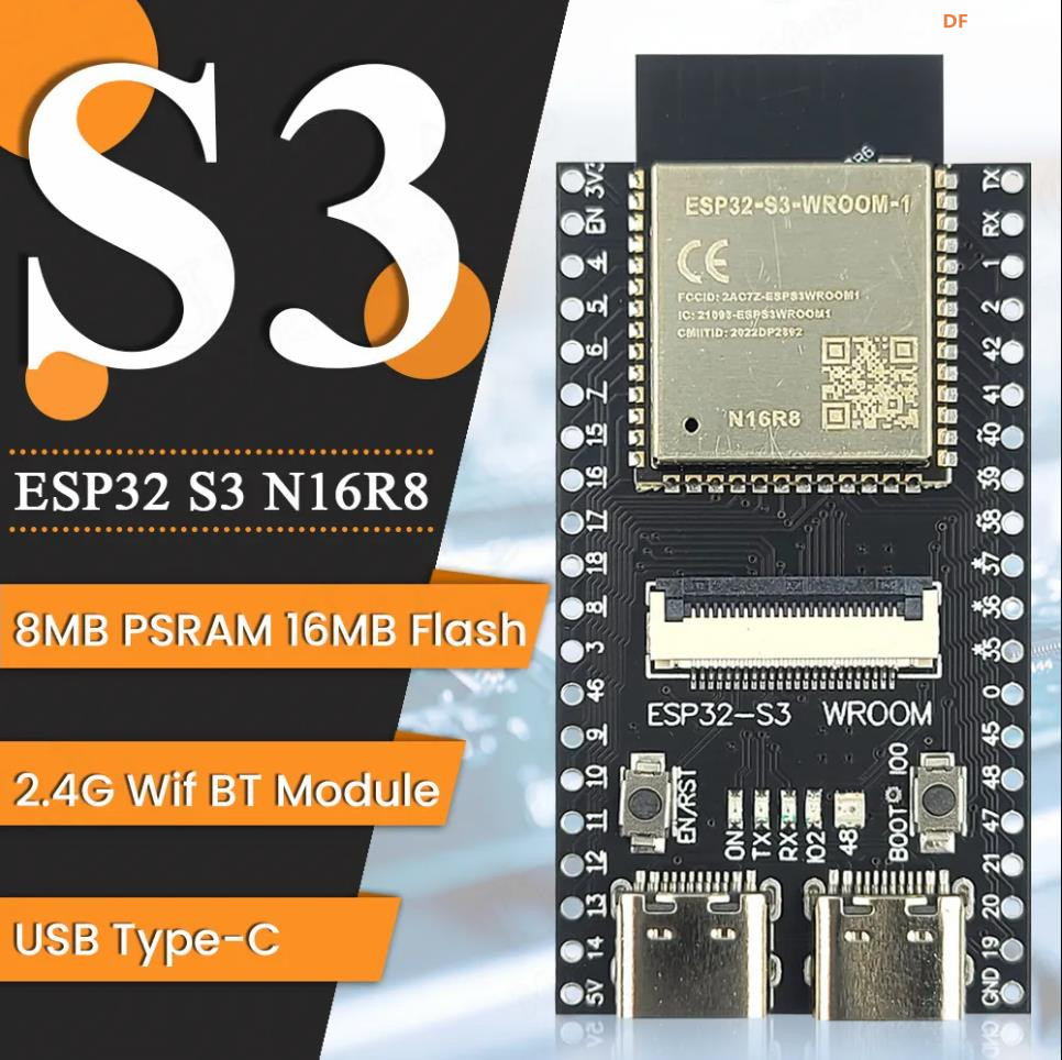
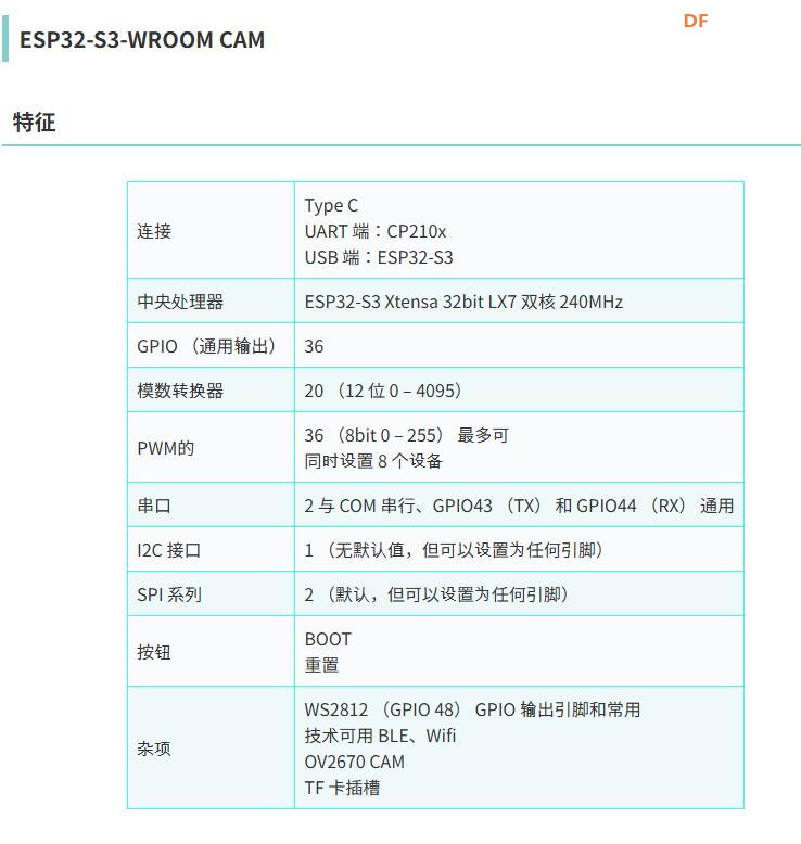
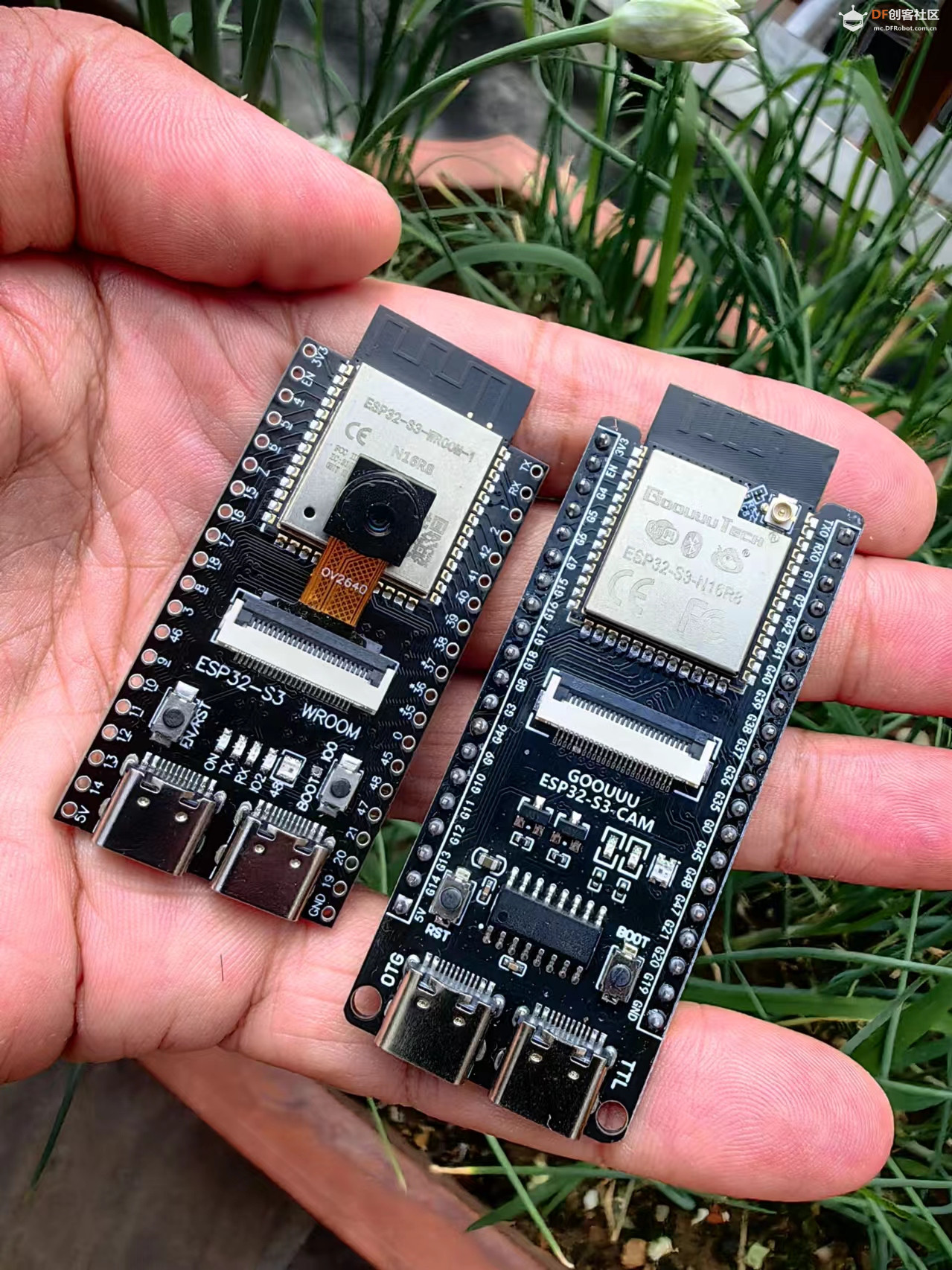
- 实验二百三十二:ESP32-S3 WROOM N16R8 CAM开发板WiFi+蓝牙模块
- OV2640/5640摄像头模组
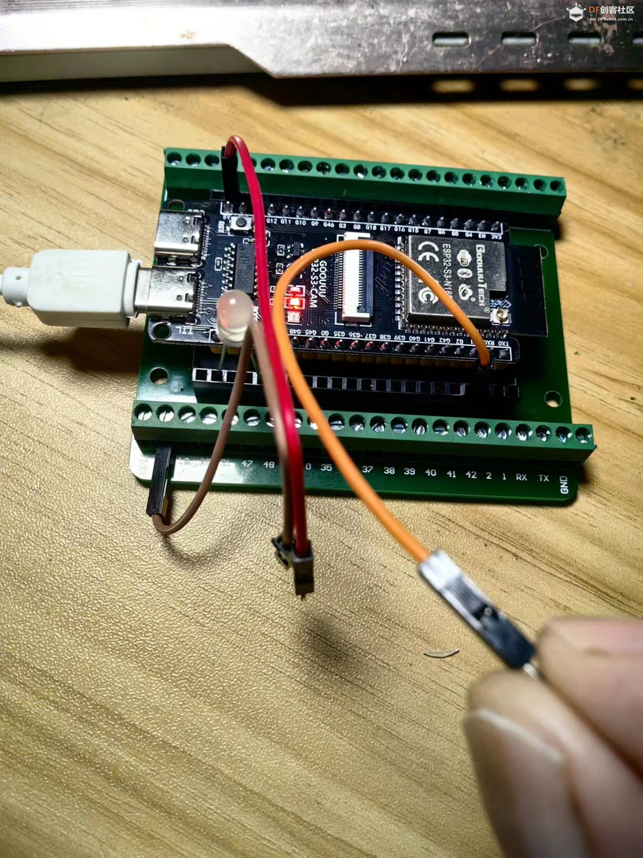
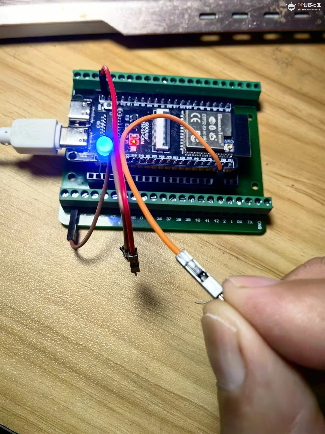
- {花雕动手做}项目之二十二:使用ESP32-S3 CAM的触摸传感器来创建触摸开关LED灯
- */
-
- #define PIN_LED 21 // 定义LED连接的引脚为21
- #define PRESS_VAL 80000 // 设置触摸检测的阈值
- #define RELEASE_VAL 30000 // 设置释放检测的阈值
-
- bool isProcessed = false; // 定义一个布尔变量用于记录触摸状态是否已处理
-
- void setup() {
- Serial.begin(115200); // 初始化串口通信,波特率为115200
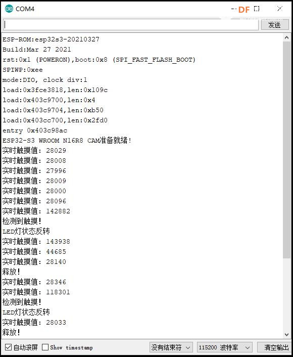
- Serial.println("ESP32-S3 WROOM N16R8 CAM准备就绪! ");
- pinMode(PIN_LED, OUTPUT); // 设置LED引脚为输出模式
- }
-
- void loop() {
- int touchValue = touchRead(T1); // 读取触摸传感器的值
- Serial.printf("实时触摸值: %d \r\n", touchValue); // 打印实时触摸值
-
- if (touchValue > PRESS_VAL) { // 如果读取到的触摸值大于触摸阈值
- if (!isProcessed) { // 如果触摸状态未处理
- isProcessed = true; // 设置触摸状态为已处理
- Serial.println("检测到触摸!"); // 打印触摸检测信息
- Serial.println("LED灯状态反转");
- reverseGPIO(PIN_LED); // 反转LED引脚的状态
- }
- }
- if (touchValue < RELEASE_VAL) { // 如果读取到的触摸值小于释放阈值
- if (isProcessed) { // 如果触摸状态已处理
- isProcessed = false; // 设置触摸状态为未处理
- Serial.println("释放!"); // 打印释放检测信息
- }
- }
- delay(500); // 延迟500毫秒
- }
-
- void reverseGPIO(int pin) {
- digitalWrite(pin, !digitalRead(pin)); // 反转指定引脚的状态
- }
| 


 沪公网安备31011502402448
 置顶卡
置顶卡 变色卡
变色卡 千斤顶
千斤顶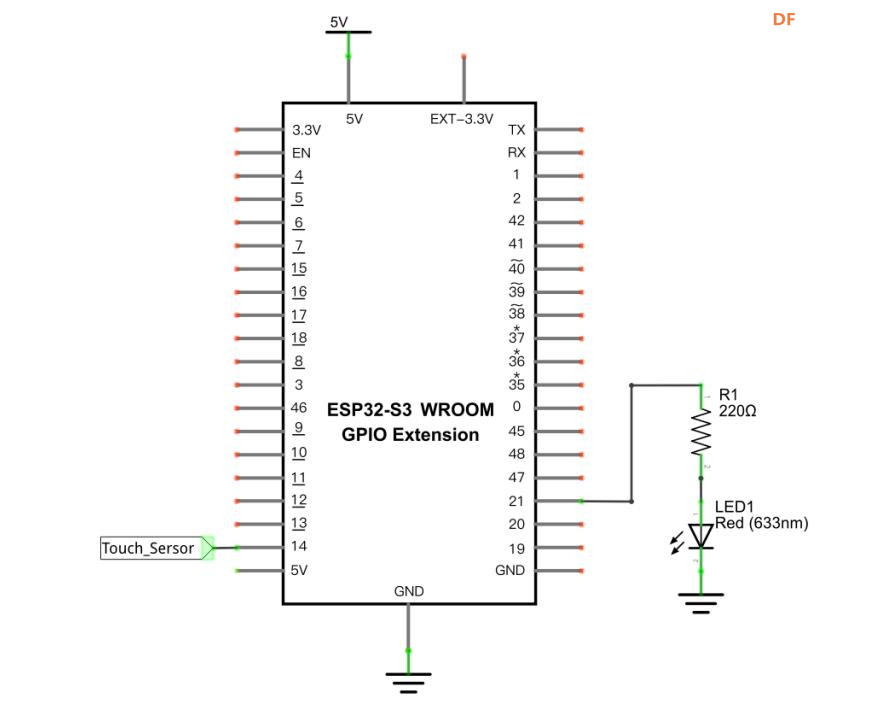

 萌萌哒新人
萌萌哒新人
 活跃会员
活跃会员
 宣传大使
宣传大使
 牛X认证
牛X认证
 创作达人
创作达人
 ARD DAY
 摸鱼团员
摸鱼团员
 志“童”道合
 编辑选择奖
编辑选择奖