本帖最后由 France 于 2022-11-14 14:08 编辑
我的家门口对着马路,所以我装了个大门,但是每次开车进出门都得自己下来打开关闭,这实在是太不方便了。网上看了下自动门的价格,额,还是自己动手做个吧! 我之前做了一版,但这次我又做了次改进。我用了新升级内置了霍尔传感器的线性执行器,新的ESP32主板,每个通道可达到15A@13.8V的新双电机驱动器模块,以及新的防水超声波传感器。
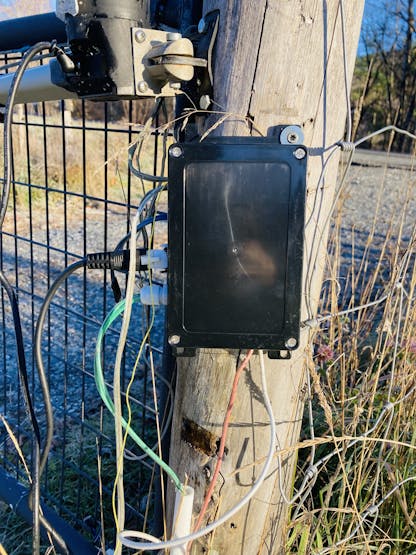
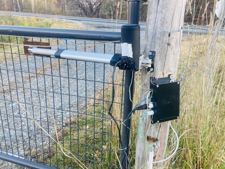
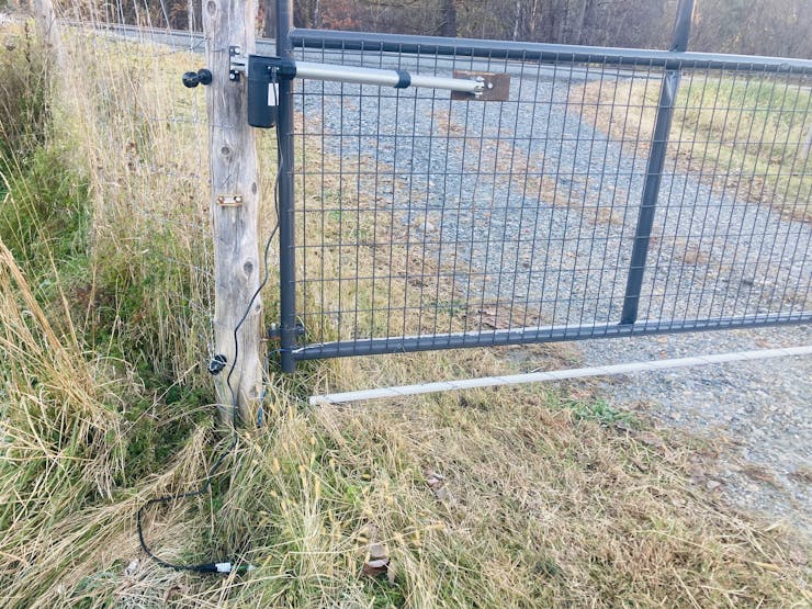
这就是最后的效果:
材料清单如下:
5. 防水柔性LED灯带 ×2 6. LD1117V33 电源管理芯片 ×1 7. 10 µF电容 ×2 8. 12V 350W 电源 ×1 9. 霍尔线性执行器 12V/12A IP65 ×2 软件 10. NPN mos管 ×4
软件平台
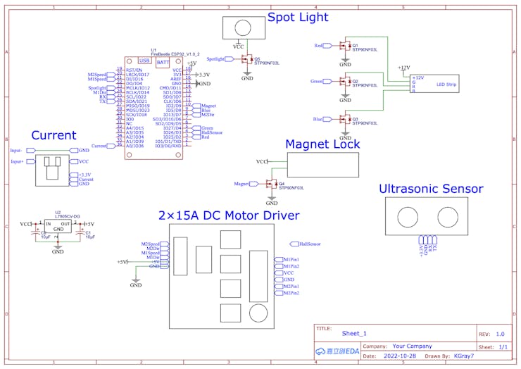
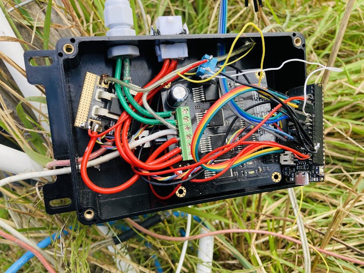
工具 接线看起来很复杂,但是你真正上手时会发现其实还好。本项目对应的接线如下:
电机驱动板 – FireBeetle 主板:
- M2Speed - IO17
- M2Dir - IO13
- M1Speed - IO16
- M1Dir - IO14
- +5V - VCC
- GND - GND
超声波距离传感器- FireBeetle主板:
- +3.3V - +3.3V
- GND - GND
- RX - IO22
- TX - IO21
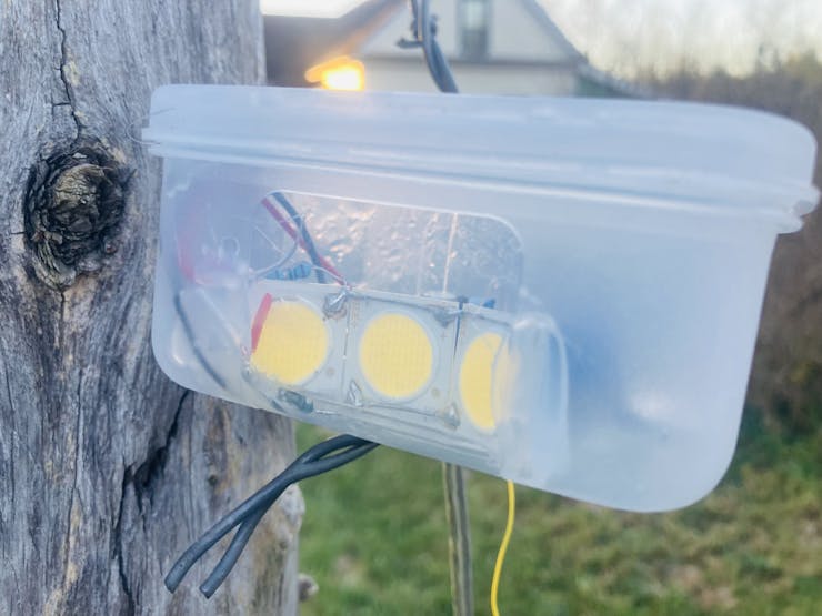
聚光灯 - FireBeetle: LED 灯带 - FireBeetle: - 第一个晶体管gate - IO25
- 第二个晶体管gate - IO27
- 第三个晶体管 gate - IO5
磁力锁- FireBeetle:
电流传感器 - FireBeetle: 具体细节参考下图:
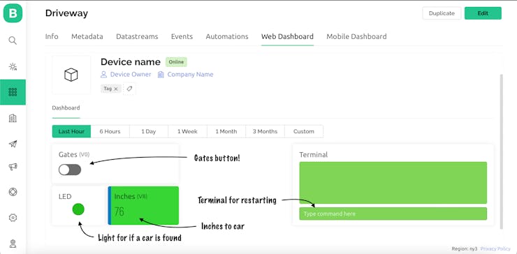
Blynk
这是桌面模板完成后的外观:
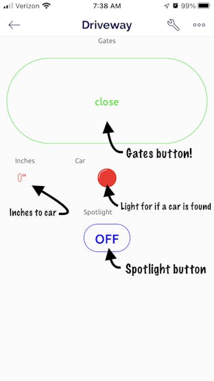
手机上的样例:
代码
这个项目的代码很长。你要用的话可能需要更改一些内容。例如,我的左执行器似乎打开得比关闭得慢,所以我必须调整打开和关闭功能来解决这个问题。 drivewaygates.ino:
- #define BLYNK_TEMPLATE_ID "************"
- #define BLYNK_DEVICE_NAME "********"
- #define BLYNK_AUTH_TOKEN "*******************************"
- #define BLYNK_PRINT Serial
首先,我们必须设置Blynk凭据。在指定的行中输入模板id、设备名称和身份验证令牌。
- #include <WiFi.h>
- #include <WiFiClient.h>
- #include <BlynkSimpleEsp32.h>
- #include <WiFiUdp.h>
- #include <ArduinoOTA.h>
- #include <SoftwareSerial.h>
接下来,我们需要的所有库都包括在内;WiFi、Blynk、OTA和软件系列。
- #define motorAspeed 16//D11
- #define motorBspeed 17//D10
- #define motorAdir 14//D6
- #define motorBdir 13//D7
- #define hall 26//D3
- #define ultra1 22
- #define ultra2 21
- #define currentIn A0
- #define pinRed D4
- #define pinGreen D3
- #define pinBlue 4//D12
- #define magnet D9//D13
- #define light 4//D12
在这里,我们定义了哪些引脚连接到哪些零件。任何不以“D”开头的引脚都是FireBeetle上的 IO口。
- /* Current Sensor (currently not working)
- const int numReadings = 30;
- float readings[numReadings]; // the readings from the analog input
- int inde = 0; // the inde of the current reading
- float total = 0; // the running total
- float average = 0; // the average
- float currentValue = 0;
- */
以下是当前传感器读数和变量,但在编写本文时,此部分不起作用。我希望尽快更新!
- int ppi = 300; //pulses per inch (for the PA-04 Linear Actuator). Change this according to your specs.
- int usedAct = 6; //inches of actuator used
- char ssid[] = "************";//WiFi network name
- char pass[] = "********";//WiFi network password
所有这些变量都必须更改!首先是ppi变量,它代表“每英寸脉冲数”。该值取决于所使用的线性执行器,一英寸对应的霍尔传感器的脉冲量。接下来是usedAct变量。该变量是使用的线性执行器上的英寸数。您可能需要多次调整此数字以获得所需效果。最后,是WiFi证书。输入您希望模块连接到的WiFi网络名称和密码。
- //Gate button value for Blynk
- int button;
- int timer;
- //current sensor value
- float voltage;
- //ultrasonic sensor
- unsigned char data[4] = {};
- float distance;
- float inches;
- int car;
- int carDist = 24;//alter this value! This value is distance in inches before something is activated
- int tim = 10000;
- long hallCount;
- //gate status flag
- boolean flag = false;
- //LED strip starting values
- int red = 255;
- int green = 255;
- int blue = 255;
这些是使用的所有其他变量。唯一需要修改的是carDist变量。这是汽车被定义为存在之前的英寸数。
- SoftwareSerial ultraSerial;
这里,我们定义了超声传感器的软件序列实例。
- BLYNK_WRITE(V0){
- button = param.asInt();
- }
- BLYNK_WRITE(V1){
- red = param.asInt();
- }
- BLYNK_WRITE(V2){
- green = param.asInt();
- }
- BLYNK_WRITE(V3){
- blue = param.asInt();
- }
- BLYNK_WRITE(V4){
- int spotlight = param.asInt();
- if (spotlight){
- digitalWrite(light, HIGH);
- }
- else {
- digitalWrite(light, LOW);
- }
- }
- String string;
- BLYNK_WRITE(V10) {
- string = param.asStr();
- if (string == "restart"){
- Blynk.virtualWrite(V10, "Restarting...");
- Serial.println("Restarting...");
- delay(2000);
- ESP.restart();
- }
- }
这些都是用于接收值的Blynk函数
- //gate status flag
- boolean isOpen = false;
这是一个布尔变量,用于指示门是打开还是关闭。
- //PWM information
- const int freq = 5000;
- const int resolution = 8;
- const int redChannel = 1;
- const int greenChannel = 2;
- const int blueChannel = 3;
- const int motorA = 4;
- const int motorB = 5;
与Arduino相比,ESP32上的PWM稍微复杂一些,但更易于定制。这里,我们设置频率、分辨率,然后设置需要PWM的信道。
- void setup() {
- Serial.begin(115200);
- ultraSerial.begin(9600, SWSERIAL_8N1, ultra1, ultra2, false); // RX, TX
- if (!ultraSerial) { // If the object did not initialize, then its configuraiton is invalid
- Serial.println("Invalid SoftwareSerial pin configuration, check config");
- }
在voidsetup()中,我们首先启动串行进行调试(请记住,只有当设备通过导线连接到您的PC时,这才有效;不要用OTA),为超声波传感器启动串行口,并检查以确保传感器已启动。
- //set pinModes
- pinMode(motorAspeed, OUTPUT);
- pinMode(motorBspeed, OUTPUT);
- pinMode(motorAdir, OUTPUT);
- pinMode(motorBdir, OUTPUT);
- pinMode(pinRed, OUTPUT);
- pinMode(pinGreen, OUTPUT);
- pinMode(pinBlue, OUTPUT);
- pinMode(hall, INPUT_PULLUP);
- pinMode(currentIn, INPUT);
- pinMode(magnet, OUTPUT);
- pinMode(light, OUTPUT);
接下来,我们设置pinmodes;除霍尔传感器外,它们都是输出,霍尔传感器是一个输入上拉。
- //attach PWM channels to the correct pins
- ledcAttachPin(pinRed, redChannel);
- ledcAttachPin(pinGreen, greenChannel);
- ledcAttachPin(pinBlue, blueChannel);
- ledcAttachPin(motorAspeed, motorA);
- ledcAttachPin(motorBspeed, motorB);
-
- //setup the PWM channels
- ledcSetup(redChannel, freq, resolution);
- ledcSetup(greenChannel, freq, resolution);
- ledcSetup(blueChannel, freq, resolution);
- ledcSetup(motorA, freq, resolution);
- ledcSetup(motorB, freq, resolution);
这里,PWM已设置。首先,我们将引脚连接到正确的通道,然后为每个通道设置通道频率和分辨率。
- //connect to the WiFi
- wificonnect();
-
- //Start Blynk
- Serial.println("Blynk Starting...");
- Blynk.config(BLYNK_AUTH_TOKEN);
-
- //Start OTA
- Serial.println("OTA Starting...");
- OTAStart();
这三个部分能让我们的无线网络正常运行。首先,我们连接到WiFi,然后配置Blynk,最后启动OTA。OTA默认密码为“maker”;这可以在OTAStart()函数中更改。
- //open the gates all the way at the beginning to set the hall sensor back at 0
- Serial.println("Begin opening...");
- delay(1000);
- beginOpen();
- hallCount = ppi*usedAct;
- isOpen = true;
- Serial.println("Attaching interrupt...");
- attachInterrupt(digitalPinToInterrupt(hall), interruptName, FALLING);//Interrupt initialization
- //then close to the correct place, keeping track of the hall count
- Serial.println("Closing to correct place...");
- close();
- Serial.println("Done closing!");
- Serial.println("Ready");
- isOpen = false;
闸门设置完成了voidsetup(); 设置,首先,闸门在不使用霍尔传感器的情况下一直打开。这就像一种校准,因为当闸门完全打开到极限时,我们就能确定霍尔传感器的位置!接下来,连接霍尔传感器,因为如果我们在打开功能开始之前连接霍尔传感器中断,霍尔传感器将开始计数,我们不想在校准时这样做。现在我们可以靠近正确的位置,一边走边计数霍尔脉冲,以确保闸门正确关闭。当它们已关闭,我们将闸门状态布尔值设置为false,表示闸门已成功关闭。
- void loop() {
- //if WiFi was lost, reconnect
- if (WiFi.status() == WL_CONNECTION_LOST){
- Serial.println("Connection lost...");
- wificonnect();
- }
- //handle the OTA
- ArduinoOTA.handle();
在voidloop()检查WiFi连接,处理OTA。
- //ultrasonic sensor reading
- for (int i=0;i<4;i++){
- Serial.println("Checkdist();");
- ArduinoOTA.handle();
- checkDist();
- }
- Blynk.virtualWrite(V8,inches);
- if (inches <= carDist){
- Serial.println("Car");
- Blynk.virtualWrite(V9, HIGH);
- }
- else {
- Blynk.virtualWrite(V9, LOW);
- }
这里,我们多次读取超声波传感器,以确保获得良好的读数。然后我们将值发送给Blynk,检查是否有车,并相应地更新Blynk的LED。
- //if Blynk button pressed, switch the flag
- if (button == HIGH){
- flag = !flag;
- }
- //check to see if the flag is true, then check if the gates are closed and open them
- if (flag == true && isOpen == false) {
- digitalWrite(magnet, LOW);
- delay(100);
- open();
- isOpen = true;
- }
- //else, check to see if the gates are open, and close them
- else if (flag == false && isOpen == true) {
- close();
- delay(100);
- digitalWrite(magnet, HIGH);
- isOpen = false;
如果按下Blynk的“门”按钮,则切换标志。如果标志为真,且闸门关闭,磁铁闭合,打开闸门,并将状态设置为打开!如果标志为假且闸门打开,关闭闸门,磁铁打开,并将状态设置为关闭。
- //write the Blynk values to the LED strips
- ledcWrite(redChannel, red);
- ledcWrite(greenChannel, green);
- ledcWrite(blueChannel, blue);
-
- //run Blynk, yield() to prevent unwanted resets, and delay 1 millisecond to keep track of time
- Blynk.run();
- yield();
- delay(1);
在voidloop()的最后一部分中,Blynk值被写入LED灯带中,Blynk运行,我们确保yield();如果我们不增加yield,ESP32将意外重启,并可能导致问题。
- void wificonnect(){
- Serial.println("WiFi Connecting...");
- WiFi.mode(WIFI_STA);
- WiFi.begin(ssid, pass);
- while (WiFi.status() != WL_CONNECTED){
- Serial.print(".");
- delay(1000);
- }
- Serial.println("");
- while (WiFi.waitForConnectResult() != WL_CONNECTED) {
- Serial.println("Connection Failed! Rebooting...");
- delay(5000);
- ESP.restart();
- }
- }
-
- void checkDist(){
- retry:
- do {
- for (int i = 0; i < 4; i++){
- data[i] = ultraSerial.read();
- }
- }
- while (ultraSerial.read() == 0xff);
- ultraSerial.flush();
- if (data[0] == 0xff) {
- int sum;
- sum = (data[0] + data[1] + data[2]) & 0x00FF;
- if (sum == data[3]) {
- distance = (data[1] << 8) + data[2];
- if (distance > 20) {
- inches = distance / 25.4; //mm to inches
- Serial.print(distance / 10);
- Serial.println("in");
- } else {
- inches = 0;
- Serial.println("Below the lower limit");
- }
- } else goto retry;//Serial.println("ERROR");
- }
- delay(100);
- }
-
- void beginOpen(){
- bodo:
- digitalWrite(motorAdir, HIGH);
- digitalWrite(motorBdir, HIGH);
- ledcWrite(motorA, 255);
- ledcWrite(motorB, 255);
- yield();
- timer++;
- delay(1);
- while (timer < 24000){
- yield();
- goto bodo;
- }
- timer = 0;
- Serial.println("Done!");
- ledcWrite(motorA, 0);
- ledcWrite(motorB, 0);
- }
-
- void open(){
- int times=0;
- hallCount = 0;
- redo:
- digitalWrite(motorAdir, HIGH);
- digitalWrite(motorBdir, HIGH);
- ledcWrite(motorA, 255);
- ledcWrite(motorB, 255);
- while (hallCount < ppi*usedAct){
- yield();
- Serial.print("Hall count: ");
- Serial.println(hallCount);
- goto redo;
- }
- delay(500);
- tedo:
- digitalWrite(motorAdir, HIGH);
- digitalWrite(motorBdir, HIGH);
- ledcWrite(motorA, 255);
- ledcWrite(motorB, 255);
- times++;
- delay(1);
- yield();
- while (times < 7000){
- goto tedo;
- }
- times=0;
- yield();
- ledcWrite(motorA, 0);
- ledcWrite(motorB, 0);
- }
-
- void close(){
- hallCount = ppi*usedAct;
- redone:
- digitalWrite(motorAdir, LOW);
- digitalWrite(motorBdir, LOW);
- ledcWrite(motorA, 255);
- ledcWrite(motorB, 255);
- while (hallCount > 0){
- yield();
- Serial.print("Hall count: ");
- Serial.println(hallCount);
- goto redone; //goto endy;
- }
- yield();
- ledcWrite(motorA, 0);
- ledcWrite(motorB, 0);
- digitalWrite(motorAdir, HIGH);
- digitalWrite(motorBdir, HIGH);
- Serial.println("Gates closed");
- }
-
- void OTAStart(){
- // Port defaults to 8266
- ArduinoOTA.setPort(8266);
- // Hostname defaults to esp8266-[ChipID]
- ArduinoOTA.setHostname("DrivewayESP");
- // No authentication by default .
- ArduinoOTA.setPassword("maker");
- // Password can be set with it's md5 value as well
- // MD5(admin) = 21232f297a57a5a743894a0e4a801fc3
- // ArduinoOTA.setPasswordHash("21232f297a57a5a743894a0e4a801fc3");
- ArduinoOTA.onStart([]() {
- //open();
- String type;
- if (ArduinoOTA.getCommand() == U_FLASH) {
- type = "sketch";
- } else { // U_FS
- type = "filesystem";
- }
- // NOTE: if updating FS this would be the place to unmount FS using FS.end()
- Serial.println("Start updating " + type);
- });
- ArduinoOTA.onEnd([]() {
- Serial.println("\nEnd");
- });
- ArduinoOTA.onProgress([](unsigned int progress, unsigned int total) {
- Serial.printf("Progress: %u%%\r", (progress / (total / 100)));
- });
- ArduinoOTA.onError([](ota_error_t error) {
- Serial.printf("Error[%u]: ", error);
- if (error == OTA_AUTH_ERROR) {
- Serial.println("Auth Failed");
- } else if (error == OTA_BEGIN_ERROR) {
- Serial.println("Begin Failed");
- } else if (error == OTA_CONNECT_ERROR) {
- Serial.println("Connect Failed");
- } else if (error == OTA_RECEIVE_ERROR) {
- Serial.println("Receive Failed");
- } else if (error == OTA_END_ERROR) {
- Serial.println("End Failed");
- }
- });
- ArduinoOTA.begin();
- Serial.println("Ready");
- Serial.print("IP address: ");
- Serial.println(WiFi.localIP());
- }
-
- ICACHE_RAM_ATTR void interruptName() {
- if (isOpen == false){
- hallCount++;
- if (hallCount >= ppi*usedAct){
- //ledcWrite(motorA, 0);
- //ledcWrite(motorB, 0);
- digitalWrite(hall, HIGH);
- hallCount = ppi*usedAct;
- //delay(1000);
- }
- }
- else if (isOpen == true){
- hallCount--;
- if (hallCount <= 0){
- ledcWrite(motorA, 0);
- ledcWrite(motorB, 0);
- digitalWrite(hall, HIGH);
- hallCount = 0;
- //delay(1000);
- }
- }
- //currentVal();
- }
这些都是我为简化代码而做的所有函数。注意最后一个函数有什么不同吗?这就是中断函数。有关ESP32中断的更多信息,请查看此链接。
原出处:https://www.hackster.io/k-gray/automated-driveway-gates-version-2-6d9b2e
| 


 沪公网安备31011502402448

 置顶卡
置顶卡 变色卡
变色卡 千斤顶
千斤顶
 ~·~
~·~